VACUUM TECHNIQUES
1. Important Pressure Units and Quantities
1. A. Common pressure units
|
1 Torr = 1 mm Hg at 0°C, standard gravity 1 atm = 760 Torr 1 micron = 1 mm Hg = 10-3 Torr = 1mTorr |
1. B. Mean free path
The mean free path l is the average distance traveled by a gas molecule between collisions with other molecules.
The formula for l is given by Eq. (12-11) in Sime and by Eq. (1-19) in Atkins, 5th Ed.
![]()
where N* is the number density of the gas
![]()
and d is the molecular diameter.
|
Example: |
Calculate the mean free path of a nitrogen molecule at 1 Torr, 298 K. (Nitrogen, which makes up 80% of the atmosphere, has a molecular diameter of 3.7Å)
|
Observe that mean free path is inversely proportional to pressure:

Thus, one can easily calculate l at any pressure if one knows its value at one pressure.
|
Example: |
Calculate the mean free path of a nitrogen molecule at 1 mTorr (10-3 Torr) , 298 K.
|
For making quick approximations of l, physical chemists memorize one value of the free path (5 cm at 1 mTorr = 10-3 Torr) and use the fact that mean free path is inversely proportional to pressure to calculate l at any pressure.
1. C. Importance of mean free path
Mean free path is a key property in vacuum system design.
|
The changeover occurs at 10-2 - 10-3 Torr for typical vacuum systems.
2. Vacuum System Components
2. A. Pumps
2. A. i. Aspirator
|
|
Principle of operation: Bernoulli’s Principle (moving fluid reduces pressure)
Pump operation is based on bulk flow of fluids
Ultimate vacuum is approximately 24 Torr (vapor pressure of water at 25°C) |
2. A. ii. Rotary oil pump
|
|
Principle of operation:
Pump operation is based on bulk flow of gas; hence the pump works in the viscous flow regime
Used for obtaining "rough" vacuum (10-3 Torr), which is the lower limit of the viscous flow regime
|
Safety considerations:
2. A. iii. Diffusion pump
|
|
Principle of operation: momentum transfer by vapor jet stream
Individual molecules are "pushed" toward exhaust by jet stream; hence, the pump works in the molecular flow regime
Used for obtaining "high" vacuum (10-6 Torr)
|
Safety considerations:
2. A. iv. Other pumps
Turbomolecular pump: ultra-fast fan blades knock molecules out of vacuum system
Cryo pump: molecules are frozen out
Sorption pump: molecules diffuse into absorbing material
Sputter ion pump: molecules are ionized and buried
2. B. Cold trap
|
|
Purpose:
Principle of operation: freeze out contaminants
|
Safety considerations:
|
Demo: |
Put a test tube into a dewar of liquid nitrogen; condense liquid oxygen |
2. C. Pressure gauges
2. C. i. Barometer
|
|
Uses the height of a column of mercury to measure ambient atmospheric pressure
patm = h
|
2. C. ii. Manometer
|
|
Uses the height difference of a mercury column to measures system pressure relative to ambient atmospheric pressure
patm = psys + Dh
psys = patm - Dh
|
Safety considerations:
2. C. iii. Thermocouple gauge
Principle of operation: pressure dependence of thermal conductivity.
Only works at relatively high pressures because thermal conductivity eventually becomes too small.
2. C. iv. Capacitance manometer
Principle of operation: mechanical deflection of membrane (which is one plate of a capacitor) alters capacitance in an electronic circuit
Only works at relatively high pressures because deflection eventually becomes too small.
2. C. v. Ionization gauge
Principle of operation: ionization of gas by a high voltage results in a current of charges particles
Only works at low pressures because high voltage causes gas breakdown (lightning bolts) at higher pressures.
2. D. Regulators
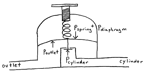
Gas flow from a pressurized cylinder is controlled with
1) Main cylinder valve
2) Pressure regulator
3) Outlet valve
Valves are either open or closed; when open, the pressure is equal on both sides (assuming no or slow gas flow). The regulator allows for an adjustable pressure difference between both sides.

The cylinder pressure pcylinder forces the valve closed and seals the regulator. The valve is attached to a flexible diaphragm that is connected to the pressure adjusting spring, which exert opening pressures pdiaphragm and pspring on the valve, respectively. Compressing the spring pushes against the diaphragm and valve, allowing gas from the cylinder to flow past the valve. This gas exerts closing pressure poutlet against the diaphragm, which closes the regulator. At equilibrium the opening and closing pressures balance each other
pcylinder + poutlet = pspring + pdiaphragm
Thus, an increase in the spring pressure causes an increase in the outlet gas pressure.
Safety considerations:
2. E. Valves and stopcocks
Solid stopcocks are satisfactory for rough and low vacuum work.
Vacuum-backed or o-ring stopcocks must be used for high vacuum work.
Safety considerations:
3. Homework Exercise
Choose one vacuum system in use the Chemistry Department and report on